In this tutorial you will learn how to use BH-1750 ambient light sensor with Visuino.
The values from the sensor will be displayed in Visuino Instrument for better visualization.
Watch the Video!
This project was made by Visuino user Rafał. Visit his youtube channel here: https://www.youtube.com/@Edappl/videos
Step 1: What You Will Need
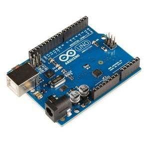
- Arduino UNO or Arduino Mega (or any other board)
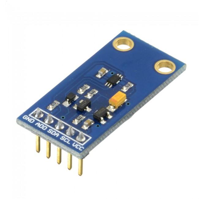
- BH-1750 ambient light sensor
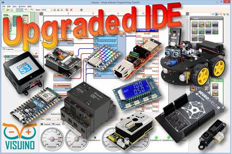
- Visuino program: Download Visuino
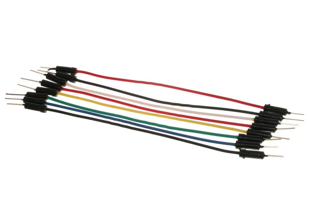
- Jumper wires
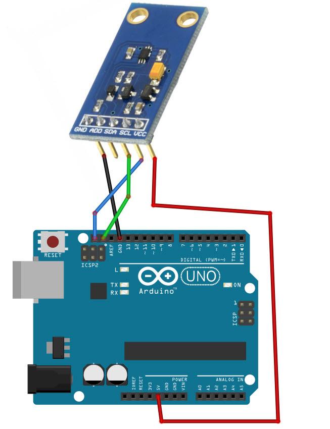
Step 2: The Circuit
- Connect BH-1750 Sensor pin [SCL] to Arduino pin [SCL]
- Connect BH-1750 Sensor pin [SDA] to Arduino pin [SDA]
- Connect BH-1750 Sensor pin [VCC] to Arduino pin [5v]
- Connect BH-1750 Sensor pin [GND] to Arduino pin [GND]
Step 3: Start Visuino, and Select the Arduino UNO Board Type
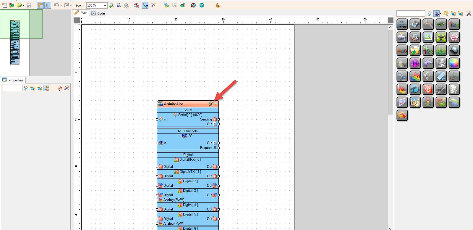
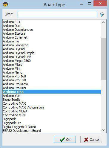
Start Visuino as shown in the first picture Click on the “Tools” button on the Arduino component (Picture 1) in Visuino When the dialog appears, select “Arduino UNO” as shown on Picture 2
Step 4: In Visuino Add Components
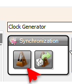
- Add “Clock Generator” component
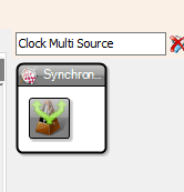
- Add “Clock Multi Source” component
- Add “ROHM BH1750 Ambient Light Sensor (I2C)” component
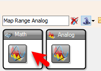
- Add “Map Range Analog” component
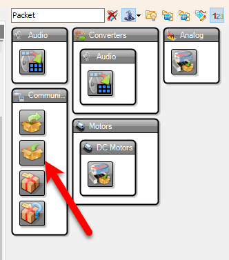
- Add “Packet” component

Step 5: In Visuino Set Components
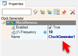
- Select “ClockGenerator1” and in the properties window set “Frequency” to 10
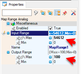
- Select “MapRange1” and in the properties window set “Input Range” > “Max” to 54612 and “Output Range” > “Max” to 100
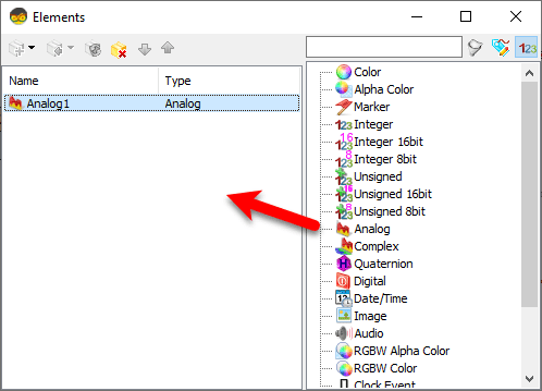
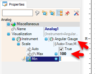
- Double click on “Packet1” and in the Elements window drag “Analog” to the left side and in the properties window set “Visualization” > “Scale” > “Max” to 100
Note: you can adjust the MapRange1 output Max and Packet1 Analog1 Scale Max according to your needs
also you can change the “Instrument” to something else
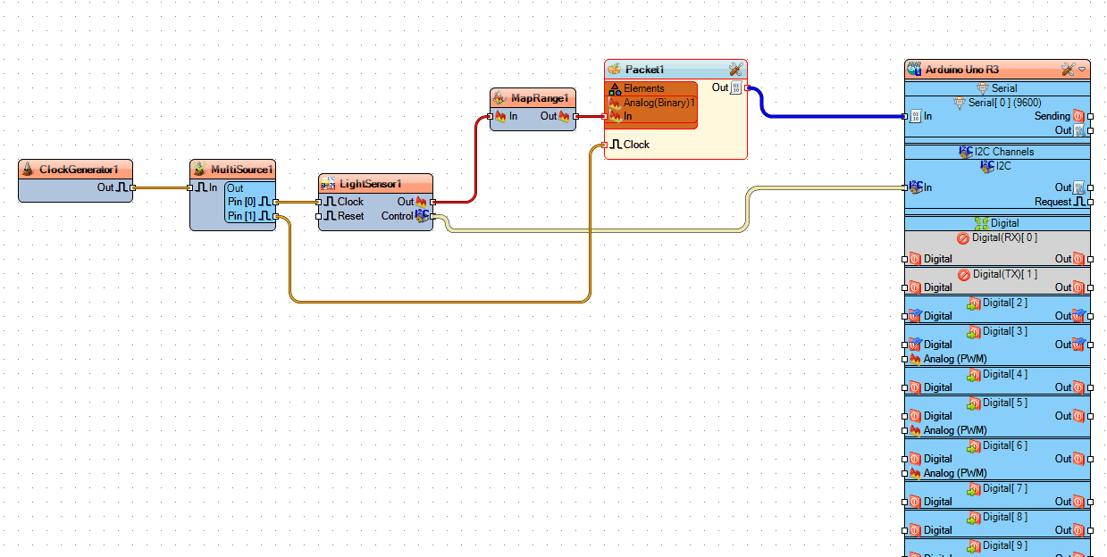
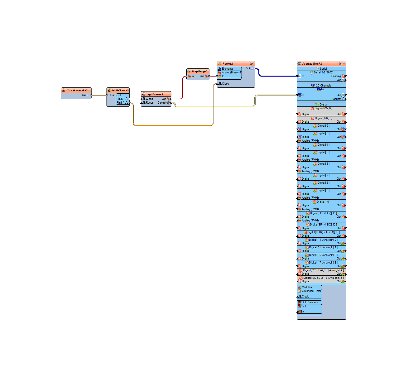
Step 6: In Visuino Connect Components
- Connect “ClockGenerator1” pin [Out] to “MultiSource1” pin [In]
- Connect “MultiSource1” pin [0] to “LightSensor1” pin [Clock]
- Connect “MultiSource1” pin [1] to “Packet1” pin [Clock]
- Connect “LightSensor1” pin [Out] to “MapRange1” pin [In]
- Connect “LightSensor1” pin [I2C] to Arduino pin [I2C]
- Connect “MapRange1” pin [Out] to “Packet1” > “Analog1” pin [In]
- Connect “Packet1” pin [Out] to Arduino serial 0 pin [In]
Step 7: Generate, Compile, and Upload the Arduino Code

Step 8: Play
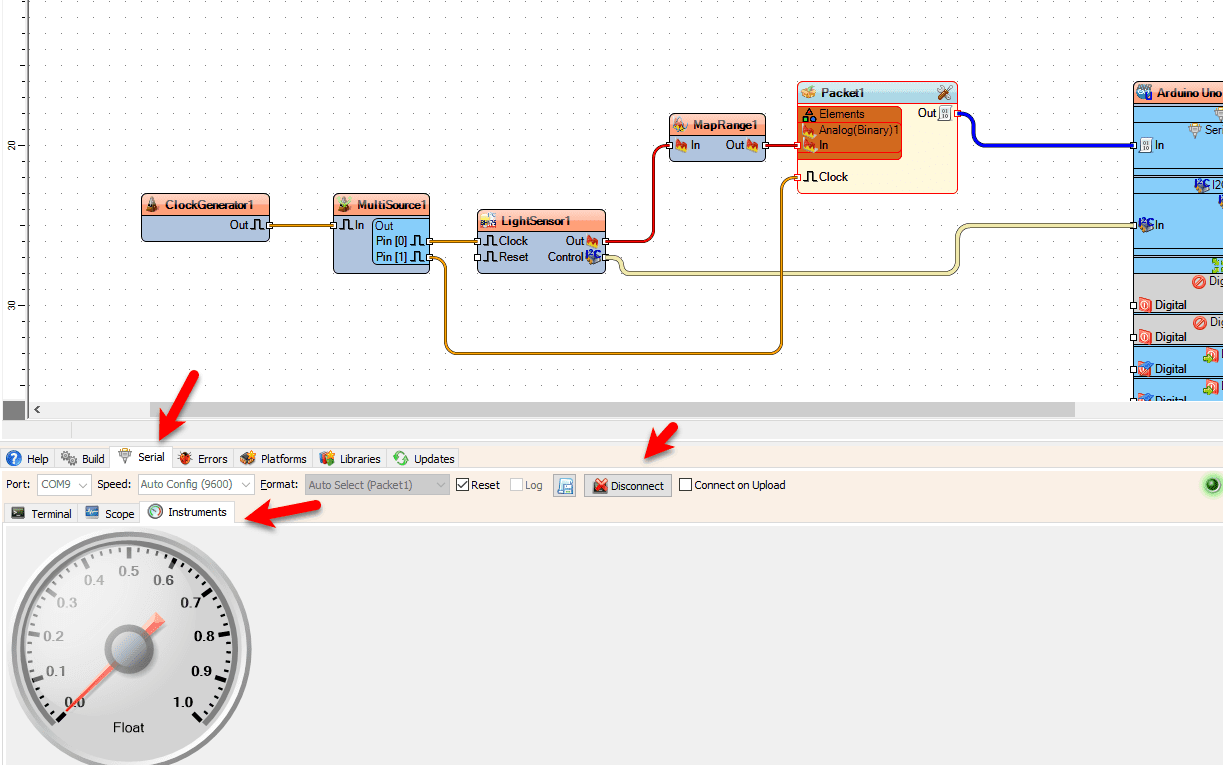
If you power the Arduino module, at the bottom click on the “Serial” Tab > “Instruments“, make sure you selected the correct port and click “Connect” button. You should start to see the values from the sensor.
Since the “ClockGenerator1” frequency is 10Hz we are getting values 10x every second, you can adjust the Frequency of the “ClockGenerator1” in the properties window.
Congratulations! You have completed your project with Visuino. Also attached is the Visuino project, that I created for this Instructable, you can download it here and open it in Visuino: https://www.visuino.eu


 English
 Czech
Czech Croatian
 Danish
 Dutch
Dutch Finnish
 French
 German
 Greek
Greek Hungarian
 Italian
 Latvian
 Norwegian
 Arabic
 Chinese (Simplified)
 Lithuanian
 Luxembourgish
 Polish
 Portuguese
 Romanian
 Russian
 Serbian
 Slovak
 Slovenian
 Spanish
 Swedish
 Turkish
 Ukrainian