In this tutorial we will learn how to make a Pulse Generator with a Frequency Sweep.
Pulse generator will start with 1Hz and increase its frequency for 0.5Hz every second. Once it reaches 10Hz it wil stop increasing the frequency.
You can set your own Starting frequency, End frequency, Frequency increment, and the increment interval.
Step 1: What You Will Need
- Arduino UNO (or any other Arduino or ESP)
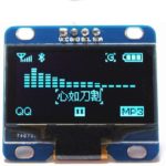
- OLED Display
- Jumper wires
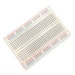
- Breadboard
- Visuino program: Download Visuino
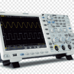
- Oscilloscope (Optional)
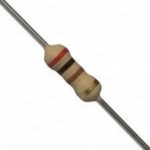
- 1KOhm resistor (Optional)
- LED (Optional)
Step 2: The Circuit Using OLED & Oscilloscope
- Connect OLED Display pin [SCL] to Arduino pin [SCL]
- Connect OLED Display pin [SDA] to Arduino pin [SDA]
- Connect OLED Display pin [VCC] to Arduino pin [5v]
- Connect OLED Display pin [GND] to Arduino pin [GND]
- Connect Oscilloscope probe to the Arduino Digital pin [2]
- Connect Oscilloscope Ground probe to the Arduino pin [GND]
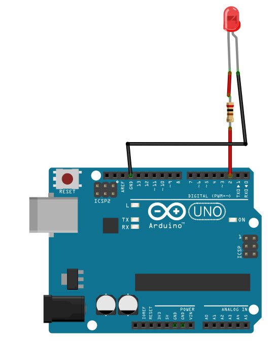
Step 3: The Circuit Using LED
- Connect Resistor 1Kohm to the Arduino Digital pin [2]
- Connect Resistor 1Kohm to (other side) to the LED [Positive pin +]
- Connect LED [Negative pin -] to the Arduino pin [GND]
Step 4: Start Visuino, and Select the Arduino UNO Board Type


The Visuino: https://www.visuino.eu also needs to be installed. Download Free version or register for a Free Trial.
Start Visuino as shown in the first picture Click on the “Tools” button on the Arduino component (Picture 1) in Visuino When the dialog appears, select “Arduino UNO” as shown on Picture 2
Step 5: In Visuino Add Components
- Add “Clock Generator” component
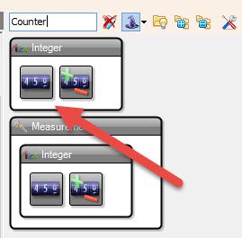
- Add “Counter” component
- Add “Analog Value” component
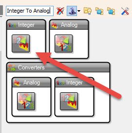
- Add “Integer To Analog” component
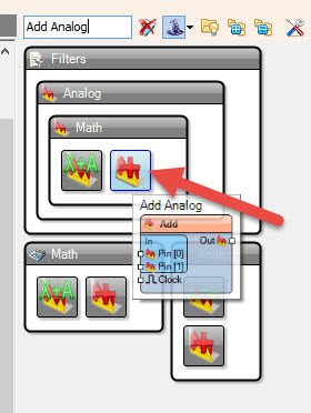
- Add “Add Analog” component
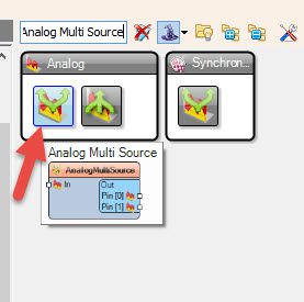
- Add “Analog Multi Source” component
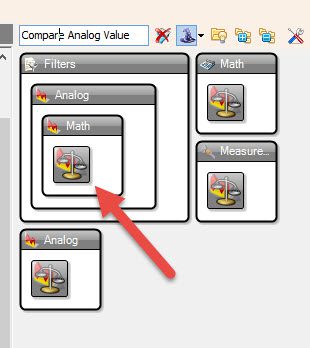
- Add “Compare Analog Value” component
- Add “Analog On/Off Switch” component
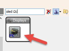
- Add “OLED I2C” component
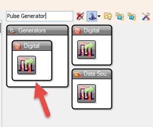
- Add “Pulse Generator” component
Step 6: In Visuino Set Components
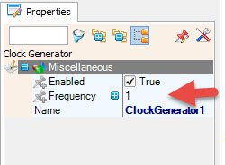
- Set the Interval: Select “ClockGenerator1” and in the properties window set frequency, in our case it is 1Hz, this means that the frequency will increase every second
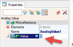
- Set Start Frequency: Select “AnalogValue1” and in the properties window set “Value“, in our case it is 1, this means that we will start with the frequency 1Hz
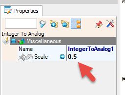
- Set Frequency Increment: Select “IntegerToAnalog1” and in the properties window set “Scale“, in our case it is 0.5, this means that the frequency will increase for 0.5Hz every time
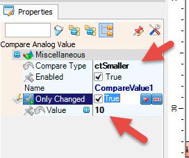
- Set End Frequency: Select “CompareValue1” and in the properties window set “Compare Type” to ctSmaller and “Value“, in our case it is 10, this means that the frequency will stop increasing at 10Hz
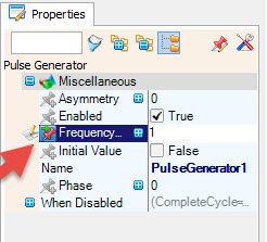
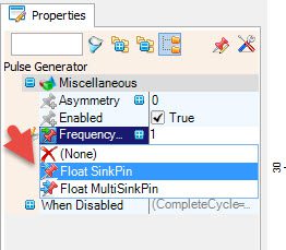
- Select “PulseGenerator1” and in the properties window select “Frequency” and click on the Pin Icon and select “Float SinkPin“
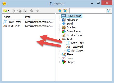
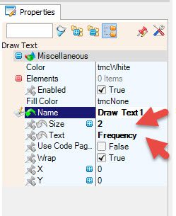
- Double click on the “DisplayOLED1” and in the “Elements” window drag “Draw Text” to the left side and in the Properties window set “Text” to “Frequency” and “Size” to 2
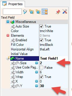
- In the “Elements” window drag “Text Field” to the left side and in the Properties window set “Size” to 2 and “Y” to 30
- Close the “Elements” window
Step 7: In Visuino Connect Components
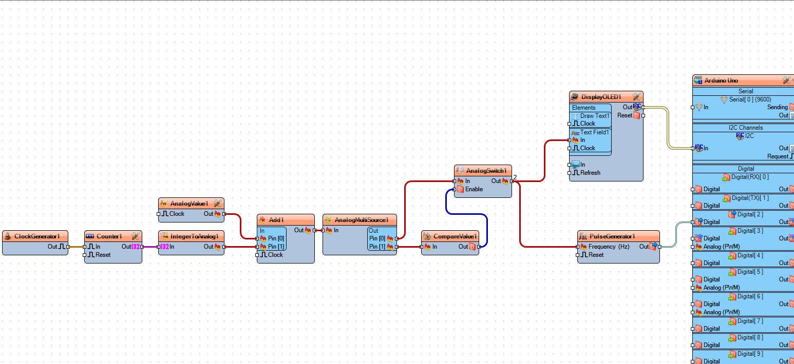
- Connect “ClockGenerator1” pin [Out] to “Counter1” pin[In]
- Connect “Counter1” pin [Out] to “IntegerToAnalog1” pin[In]
- Connect “AnalogValue1” pin [Out] to “Add1” pin[0]
- Connect “IntegerToAnalog1” pin [Out] to “Add1” pin[1]
- Connect “Add1” pin [Out] to “AnalogMultiSource1” pin[In]
- Connect “AnalogMultiSource1” pin [0] to “AnalogSwitch1” pin[In]
- Connect “AnalogMultiSource1” pin [1] to “CompareValue1” pin[In]
- Connect “CompareValue1” pin [Out] to “AnalogSwitch1” pin[Enable]
- Connect “AnalogSwitch1” pin [Out] to “PulseGenerator1” pin[Frequency]
- Connect “AnalogSwitch1” pin [Out] to “DisplayOLED1” > “Text Field1” pin[In]
- Connect “PulseGenerator1” pin [Out] to Arduino Digital pin[2]
- Connect “DisplayOLED1” pin [I2C] to Arduino pin[I2C]
Step 8: Generate, Compile, and Upload the Arduino Code

In Visuino, at the bottom click on the “Build” Tab, make sure the correct port is selected, then click on the “Compile/Build and Upload” button.
Step 9: Play
If you power the Arduino module, The OLED Display will show the increasing Frequency. If you have an Oscilloscope you can connect it to the Arduino Digital pin 2 (see wiring schematic) or connect a 1KOhm resistor and an LED (see wiring schematic) to see how pulses are increasing.
Congratulations! You have completed your project with Visuino. Also attached is the Visuino project, that I created for this tutorial, you can download it and open it in Visuino: https://www.visuino.eu
Download freq-sweep3-OLED.zip

